Even though they're quite dated now, I often quite like using "HD44780" (or compatible) LCD modules in projects I build.
They're fairly easy to drive, inexpensive and very readily available.
However, there are a few attributes which are less convenient:
- They need at least 10 I/O pins to use in the 8-bit mode
- They need a potential difference of around 5V for good contrast (and variations in this 5V will affect the contrast)
- This 5V difference could be from setting the VDD supply to 5V and the contrast pin to nearly ground, or by setting the VDD supply to 3.3V and providing a negative supply for the contrast.
To work around this, I designed a small "backpack", which provides the following:
- 3.3V to 5.0V boost (charge pump)
- SPI to parallel interface via a 74HC595
- UART / I2C to LCD via a CH32V203 RISC-V Microcontroller
- CDC connector
- PWM control of backlight and contrast
- CANbus
The board can be built either for SPI mode by omitting the CH32V203 (an STM32F0 would also work), or for UART / I2C / CANbus modes by adding it.
For driving the HD44780, the 74HC595 works very well.
It provides an 8-bit interface to the LCD (I prefer the 8-bit mode to the 4-bit mode of the HD44780, as there's no risk of the upper/lower nibbles getting out of sync), and maps nicely onto the existing signals defined by the Common Display Connector
The D7 to D0 outputs are latched on the positive edge of the latch pin (pin 12), and the HD44780 loads the data on the negative edge, making it easy to provide plenty of setup and hold time for the data.
A few notes on the schematic:
- There's a slight error with RN1. BOOT0 should be pulled down, I2C_SDA should be pulled up
- I added DIP and SOIC footprints for the TC7662 charge pump, but then later found the AP3602A.
- I'd strongly advise building only with the AP3602A.
- Keeping V_LCD near to ground (rather than negative) makes software control of the contrast much easier.
- It's regulated, so small variations in the 3.3V supply don't affect the 5V supply
- RV1 and RV2 are duplicated, but only one is required - the two symbols are to allow either a DIP or SMT potentiometer to be fitted.
- If using software control of contrast (Q1 fitted), neither RV1 nor RV2 should be fitted
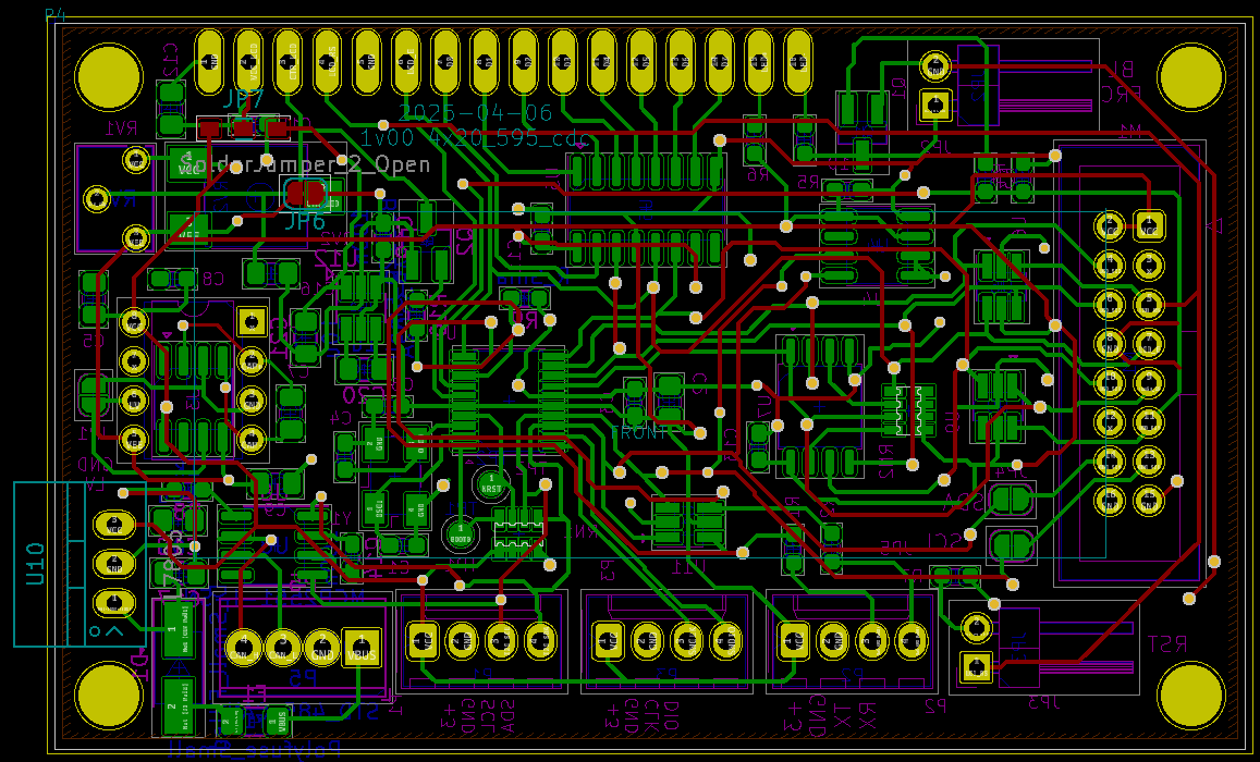
Schematics / PCB are attached: