A long time ago, I built some projects using the (then) Dallas Semiconductor 1-Wire interface.
Although this isn't an interface I generally use much today, I thought it'd be fun to build a USB to 1-Wire interface.
However, when I started designing it, I realised that I could add a few options to the board to implement much more functionality.
In the end, the board can be used for:
- USB -> 1-Wire conversion using either a CH343K or an STM32F042 (a CH32V203 should also fit in the same footprint, but I haven't tried this).
- USB -> RS485, including the DMX512 lighting control protocol and the Xpressnet model railway protocol.
- USB -> LocoNet (another model railway protocol).
- USB -> MIDI
The board is also isolated between USB and the output side, but this is only intended for convenience and avoiding ground loops, rather than safety.
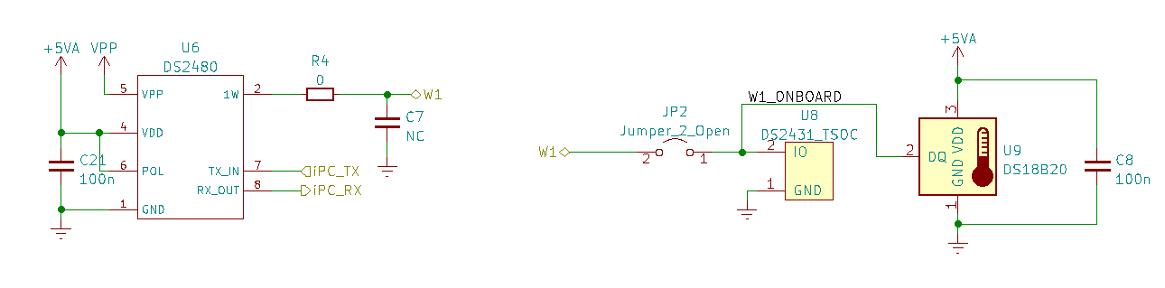
1 Wire
The 1-Wire interface is fairly simple, based on a DS2480B (with a jumper to connect an onboard DS2431 EEPROM and DS18B20 temperature sensor).
RS485
The RS485 interface is also fairly simple, consisting of an RS485 line driver and nothing else. As this board was intended for uses as a development tool rather than a finished product (and due to a lack of space on the PCB), there's no protection circuitry around the RS485 driver.
LocoNet
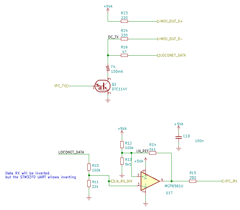
LocoNet is a model railway protocol, based on a shared open-collector bus pulled up with a current source.
The receive side is implemented using an MCP6561 comparator (the output of this comparator is inverted compared to normal UART data as this was the easiest way to select the hysteresis required by LocoNet, but this can be corrected in the STM32F0's UART).
There's also an optocoupler to allow decoding of the "LocoNet Sync" signal, connected to a timer capture channel on the STM32.
MIDI
The receive side of the MIDI interface reuses the optocoupler from the LocoNet receiver. This isn't ideal, as it's not possible to map a UART RX to this pin on the STM32, but at the relatively slow (31.25kBaud) speed of MIDI a software-based UART shouldn't be a significant issue.
The transmit side also reuses the LocoNet transmit interface, but with a higher value resistor as specified by the MIDI spec.
Misc
There are a couple of WS2812B LEDs, driven using DMA via the I2S interface.
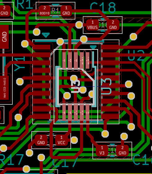
I was quite short on pins on the STM32, so ended up implementing the config DIP switches using resistors and an ADC pin.
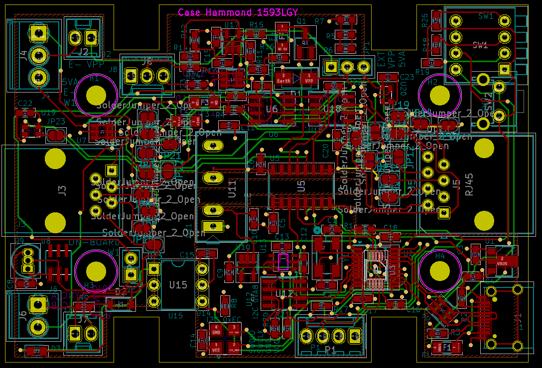
To keep the board size down, the footprint for the CH343 is placed within the footprint of the STM32F042, which works well (as only one of those two parts could ever be fitted on a board at a time):
The board also has a lot of jumpers present, to map the RJ12 and RJ45 connector pins so that they align with the various different (DMX, 1-Wire, LocoNet, XpressNet) standards.
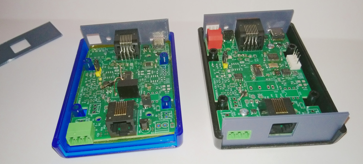
Mechanical
The PCB is designed to fit into a Hammond 1593L case, with 3D printed end plates.
The case was designed in LibreCAD and then extruded using OpenSCAD, and the OpenSCAD customiser allows the various connectors to be enabled or disabled before outputting an STL for 3D printing.
Status
I've only tested a board built as a USB -> 1-Wire interface so far, and it works, although the footprint for the DC/DC converter is incorrect.
Update 2026-01-26: I've now built one as a USB -> LocoNet interface as well. The values of R13 and R14 were incorrect (5k1) - I've updated them to 13k3 and 150k respectively.
I didn't have those parts available, but 12k7 and 152k seem to work well enough on a small LocoNet so far (I've not checked comparator thresholds and hysteresis).
Schematics / PCB: