Overview
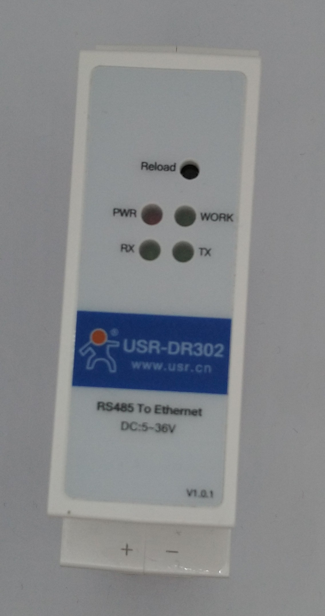
The USR302 is a very inexpensive Ethernet to RS485 bridge (with the USR301 being an Ethernet to RS232 bridge).
I bought a few, mostly intending to use them for connecting various MODBUS networks to Ethernet, but looking at the design there's some good potential for modification and customisation.
This unit would make a great starting point for an Ethernet to XpressNet (a protocol used for model railway control) gateway, or also possibly an Ethernet to DMX512 (a very common control protocol in the lighting industry) interface.
The USR301 is a bit more limited, as it does not have any of the RS232 handshaking signals.
Hardware
The hardware is based on an STM32F030CC with 256kBytes of flash and 32kB RAM, and the Ethernet MAC/PHY is a KSZ8851. There's also an SP706TE Watchdog/supply supervisor.
Note that this IC doesn't include a TCP/IP stack - that needs to be implemented on the STM32. For my initial proof-of-concept tests I used LWIP, but due to the fairly limited RAM memory must be allocated very carefully.
Note that there's a MicroUSB connector behind the DIN rail clip, but this doesn't have USB on it - it's connected to PA2 and PA3, and allows USART2 to be used for debug when the PCB is in the enclosure.
There is a 24MHz crystal for the STM32, and a 25MHz crystal for the Ethernet PHY/MAC.
There is one button (normally for reloading the configuration) and 4 LEDs (the power LED is hard wired to VCC, Rx and Tx are hard wired to the respective pins of the MCU, leaving only the "WORK" LED software controllable).
There's also a nicely labelled SWD connector on the board, although note that this is a 2.0mm pitch connector rather than 2.54mm.
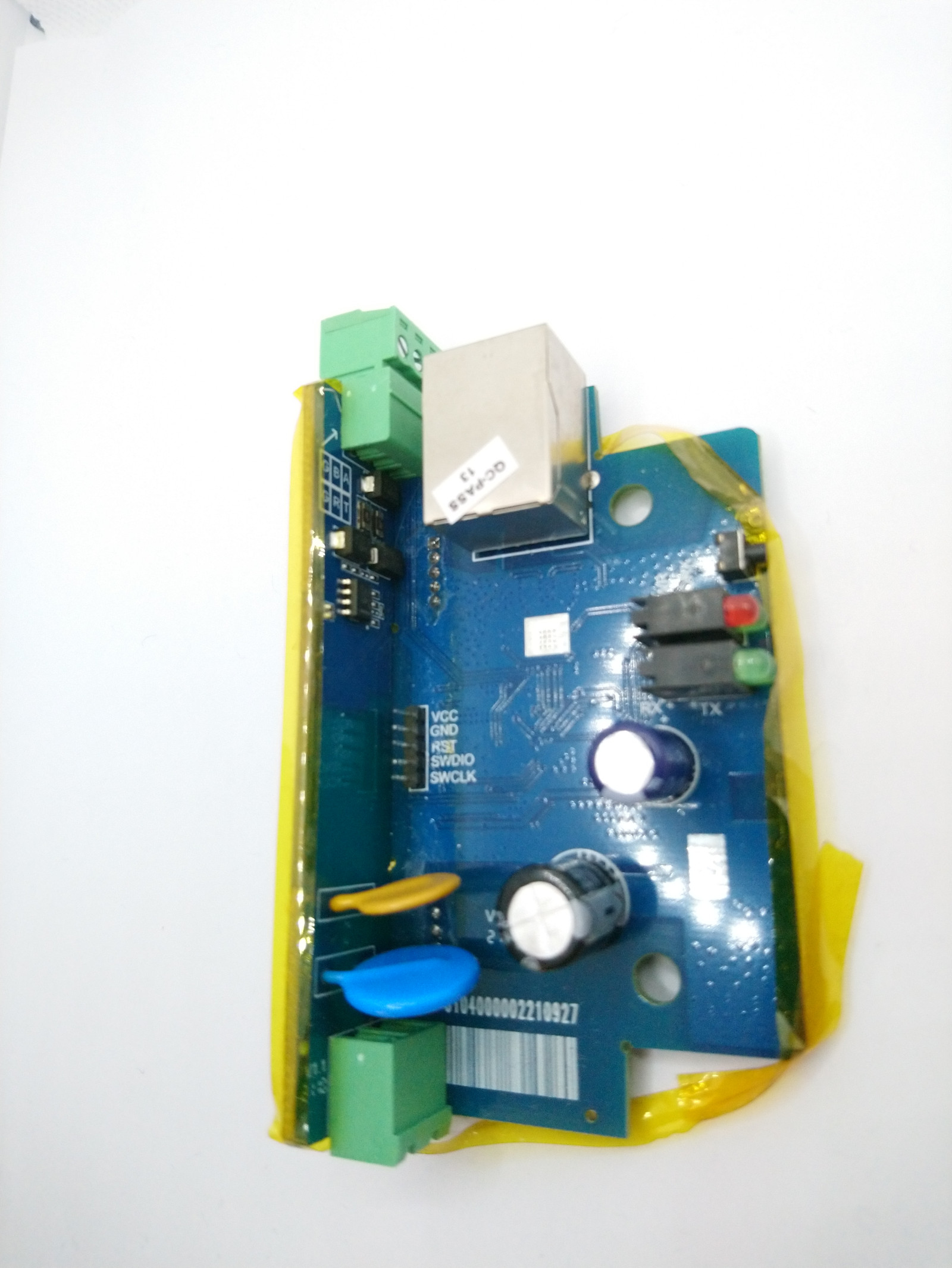

(please ignore the tape around the edge of the PCB - this was added by me to make it easier to handle the boards).
Watchdog Timers
In addition to the internal WDT on the STM32 (enabled on boot by the option bytes), this board also has an external watchdog timer (SP706TE).
The WDT reset pin is GPIOB.5, but this is also diode AND'd with the SWCLK signal on the programming header, to prevent the WDT from resetting during programming and debug.
In my case, I don't plan to use the external WDT, so I removed the two resistors highlighted in the green boxes, and during initial debug I also modified the STM32's option bytes to disable the internal WDT by default.
Pin Allocations
| Function | Pin | Resource |
|---|---|---|
| Debug TX | PA2 | USART2 (AF7) |
| Debug RX | PA3 | USART2 (AF7) |
| RS485/232 TX | PA9 | USART1 (AF1) |
| RS485/232 RX | PA10 | USART1 (AF1) |
| RS485 TXEN | PA12 | |
| Ethernet SPI SDO | PB15 | SPI2 (AF0) |
| Ethernet SPI SDI | PB14 | SPI2 (AF0) |
| Ethernet SPI SCK | PB13 | SPI2 (AF0) |
| Ethernet SPI CS | PB12 | SPI2 (AF0) |
| Ethernet SPI Reset | PB3 | |
| Ethernet SPI IRQ | PB0 | |
| Reset button | PB4 | |
| LED ('work') | PA7 |
Useful files
A very (very!) minimal proof-of-concept driver for the KSZ8851 is attached. usr30x.zip
This driver would need a bit of work before use on a production network, as at the moment it doesn't support address filtering and also doesn't check the Ethernet link status.
Note that due to third-party copyright reasons, attached is just the driver to allow the KSZ8851 to send Ethernet frames and not the LWIP driver.