In the "Decoding some signals" category, I'll be taking a look at various communication protocols (some common, some less common).
The first protocol I'll be looking at is Caller ID
NOTE: Connecting DIY electronics to your phone line is a bad idea.
All of these experiments were done using a PBX.
Side note 1 - if you've got an interest in telecoms, and don't yet own a PBX, I'd highly recommend getting one - they're great!
My favourite hobbyist PBX is probably the Panasonic KX-TDA series - units and parts are readily available, and don't require licence keys per feature). SIP ATAs are also a very good choice for caller ID experiments, as they typically allow selection of a range of different standards.
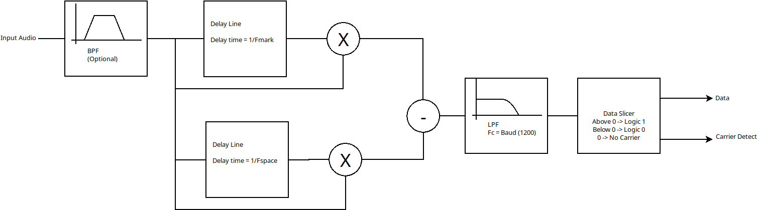
My favourite type of FSK demodulator is a "correlator" based architecture. I've found these to be simple to implement and tune, yet give good performance even on relatively noisy signals.
In a correlation based demodulator, the incoming signal is multiplied with either two local oscillators (one at the high frequency, and one at the low frequency) or two delayed copies of itself. After this, the difference of these two multiplications is low pass filtered and passed through a data slicer to produce a -1 / +1 / 0 result, allowing either low frequency, high frequency or a lack of input frequency to be determined.
In the UK, the standard for Caller ID is Openreach's SIN-227. This is very heavily based on Bellcore's "Multiple Data Message Format", but with the line polarity reversed at the start of the call, and with the caller ID information sent before the first ring. Additionally, the "v23" modulation is used, rather than Bell 202.
The PBX I have here doesn't exactly follow the SIN-227 standard (no line polarity reversal, no check for an acknowledgement before sending the caller ID tones), but it's relatively close.
To capture some caller ID tones, I used a "Ring&Tone" module to handle the interface to the phone line, and recorded the output of this with a USB sound card.
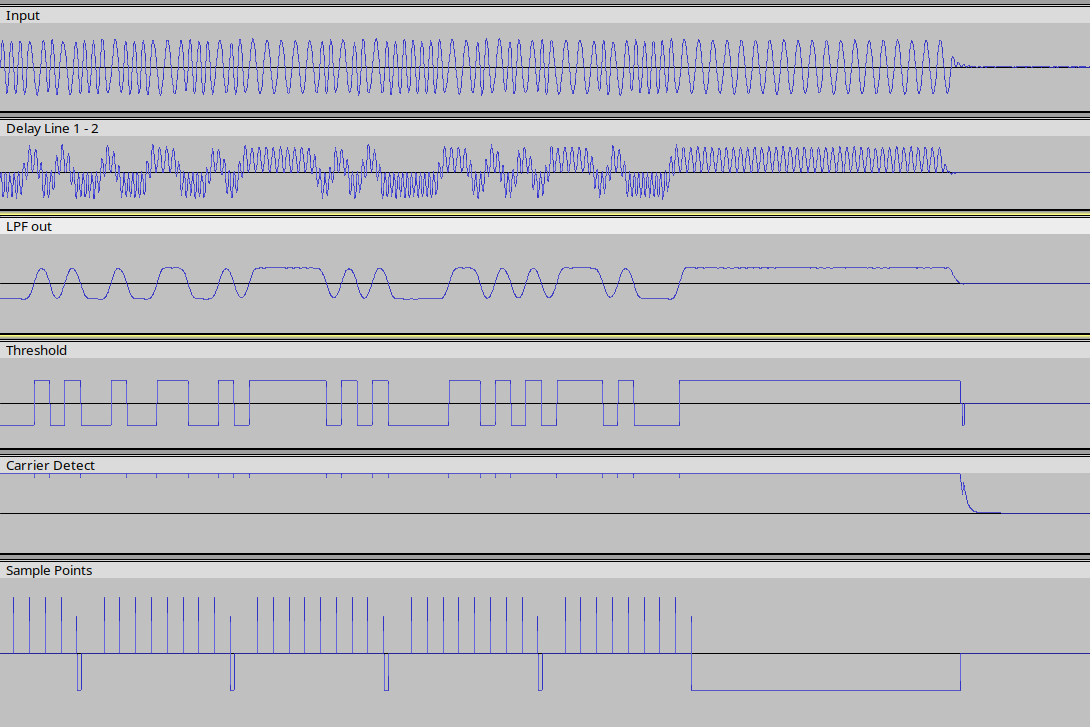
Side note 2: When debugging low frequency DSP code, I've found Audacity is a great tool for visualising data through the signal chain.
Now that we've got something that looks a lot like async serial, let's add a software UART to the caller ID decoding function, and print the text in ASCII:
Opened caller_id.wav, 689178 bytes
RX init: 0
Got end of message, 27 bytes total
80 18 01 08 30 38 31 32 31 39 31 38 02 03 32 31 30 07 07 44 48 4C 43 32 5F 58 17
Checksum status: 0
Time: '08121918' (Day=8 Month=12 Time 19:18 ) Calling DN: '210' Text: 'DHLC2_X'
Got end of message, 27 bytes total
80 18 01 08 30 38 31 32 31 39 31 38 02 03 32 30 32 07 07 44 48 4C 43 32 5F 44 2A
Checksum status: 0
Time: '08121918' (Day=8 Month=12 Time 19:18 ) Calling DN: '202' Text: 'DHLC2_D'
It works! Now all that's left is to collect groups of bytes, and arrange them in a format that allows the individual fields (time/date, called number etc) to be accessed.
Proof-of-concept code is here caller_id.zip
NOTE: this is very much proof-of-concept quality!
This code is missing error checks in a number of places, and it's also currently written for a 48kHz sampling rate. It would probably make sense to recompute the coefficients for 8kHz.