Overview
While I was debugging another project (an 80486GX processor board for the modular_cpu project), I found I needed a way to capture the internal signals of the FPGA. While some Lattice parts do support their "Reveal" logic analyser, I'm using the open-source Yosys based toolchain, so I can't use that.
I did also look at the LiteScope from LiteX, but decided that it might be easier to try building a simple logic analyser in SystemVerilog instead.
The architecture is very simple: - A trigger engine, looking for a configurable rise / fall / level on up to two of the inputs - A counter which, once triggers, steps through all of the locations in a RAM - The digital inputs to the logic analyser are connected directly to the RAM inputs - The outputs of the RAM are connected to a Wishbone bus
For the host software, I've written a python script, which accepts a configuration file listing which bit of the input bus is connected to which FPGA signal, and then communicates with the microcontroller on the modular CPU board to do wishbone reads/writes.
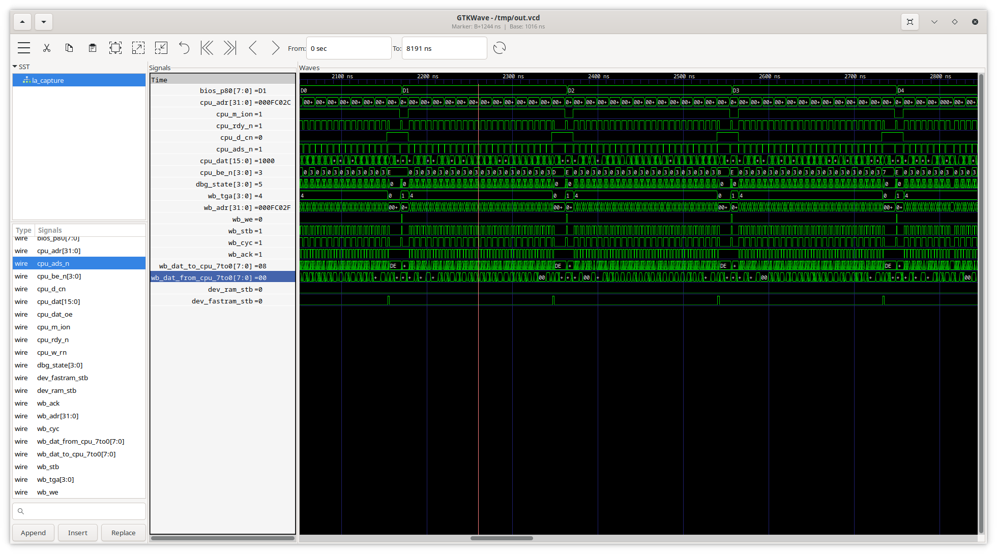
Then, after reading out all of the sample memory, the script writes a VCD file (with the signals in the VCD being specified by the config file).
I've not tested the trigger block very much (I've configured it to start capturing when the design is reset, and when testing it I've been starting from a reset each time).
This project was written very quickly, in order to help progress another project, so it's unlikely to be usable as-is - but it might be a good starting point for a similar project if you've got a requirement to build something similar.
To use this project, on the FPGA side, instantiate the logic analyser with the INPUT_W parameter set to the number of signals to be captured and CAPTURE_DEPTH to the number of samples to be captured.
Then, concatenate all of these signals into a vector and connect this to the "sig_i" input.
You'll then need some way to read and write wishbone signals from a PC. In my case, the PC issues sends commands to a microcontroller (on the modular_cpu base board), which then does a number of wishbone reads, and sends the results back.
RTL and python scripts: fpga_logic_analyser.zip