Overview
This was a project to add a number of PC compatible devices in a PC104 form factor module:
- PS2 Keyboard / Mouse
- 2x Serial Ports (one of which supports RS485)
- 1x Parallel port (supporting ECP and EPP)
- Real Time Clock
- Floppy Drive controller
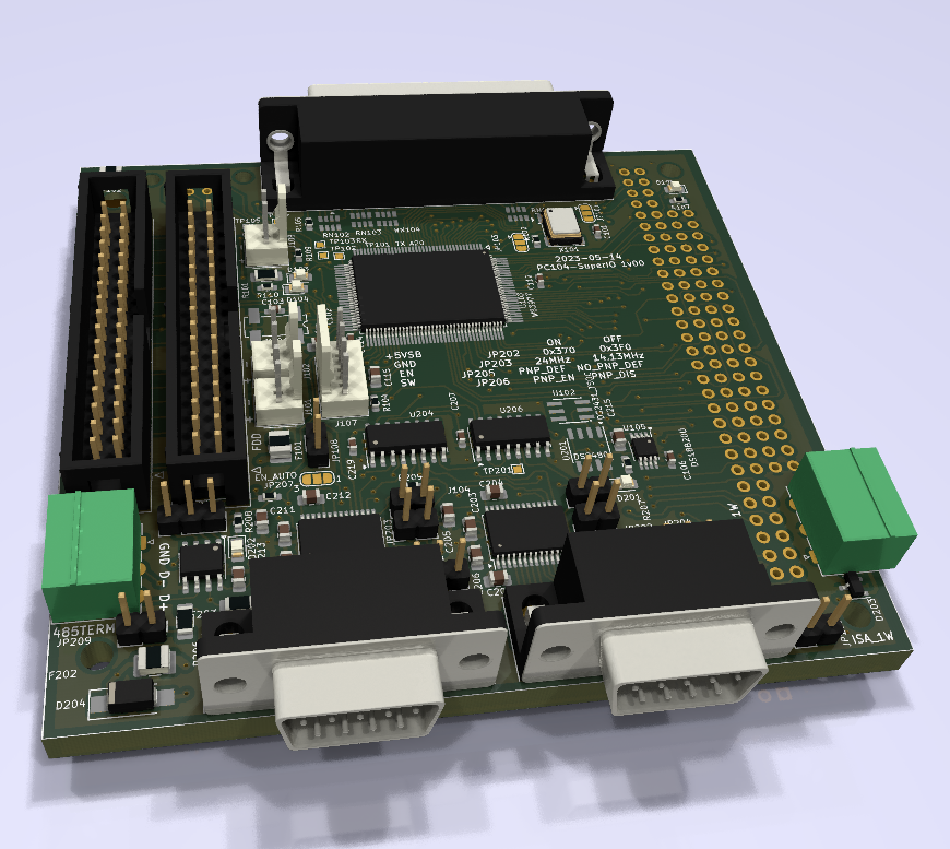
This project is based around the Winbond W83977 SuperIO chip, which seems to have been quite a popular SuperIO from ~20 years ago, and is also still reasonably available on AliExpress.
Serial Ports
The W83977 provides (at least) two serial ports, compatible with the 16550 UART. These ports also optionally have a +5V supply present on Pin 9.
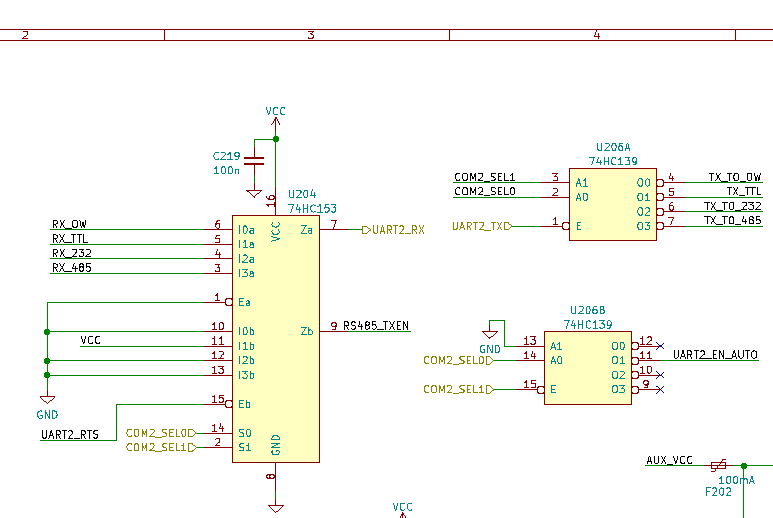
On this board, the first port supports RS232 only. The second port supports RS232, RS485, and also the 1-Wire protocol (via a DS2480). Selecting the serial port mode is done via GPIO lines from the W83977.
The 1-Wire bus has a few onboard devices present, in addition to the external connector: a DS1820 temperature sensor and a DS2431 EEPROM. Additionally, there's a jumper to allow the 1-Wire bus to be connected to IOCHK. This is a non-standard modification I've designed into a few PC104 boards, with the intention to allow a simpler implementation of plug-and-play for expansion boards that don't support standard ISA PnP.
Parallel Port
The W83977 provides one parallel port (and also the option to multiplex this into an external floppy disk interface).
This is connected via series resistors and ESD protection diodes.
PS2
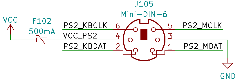
The W83977 also provides 2x PS2 controllers. These are connected to a combined 6 pin Mini-DIN connector (for space reasons), although I'm not certain I've got keyboard and mouse the correct way round.
Floppy Drive Controller
PC104-Superio has two floppy drive connectors.
These connectors are wired such that the first connector supports drives A: and B:, and the second connector supports drives B: and A:.
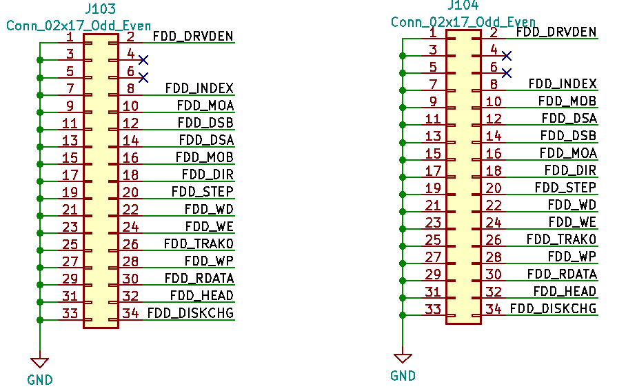
This might seem like an odd design choice, but it was done to allow 1:1 wired ribbon cables (without the twist normally seen in floppy drive cabling) to be used, if standard floppy disk cables weren't available.
NOTE: When building this board, some floppy disk cables may have a blanking pin in the space of pin 6. It's much easier to remove this pin before soldering the connectors to the board (rather than after)!
IRDA
Unfortunately, there wasn't enough space on the board for an IRDA interface.
The W83977 does support IRDA though, so the appropriate pads are routed out to test pads (TP102 and TP103).
RTC / Power Control
There's a diode for allowing the RTC battery to be trickle charged from the +5V rail, but in hindsight this facility wouldn't be useful given the absolute maximum rating on the W83977 VBAT pin being 4.0V (and lack of proper charge control circuitry). This diode should be removed when building the boards.
There's a header for controlling an ATX power supply (a +5V Standby Input, and a "Power On" output) - but I've not yet tested these. If not used, then the appropriate jumper (JP108) should be closed to allow the +5V supply to also supply the standby supply.
I2C
There were a few GPIOs left on the W83977, so I implemented a simple software-based I2C interface to a 24C32 SOT-23 I2C EEPROM. The main use for this is intended to be for storing configuration without an RTC backup battery.
Jumpers
| Reference | Pin | Function |
|---|---|---|
| JP101 | OSC_EN | Used to allow either active-high or active-low oscillator modules to be used |
| JP103 | N/A | Use either the local oscillator, or the oscillator from the ISA bus |
| JP105 | IOCHK -> W1 | Used to connect the 1-Wire bus to the PC104 IOCHK signal (non standard) |
| JP107 | ISA_RST | Connect the PC104 Reset signal to the W83977 |
| JP108 | N/A | Connect +5V to +5VSB |
| JP201 | RS485_RXEN | Connect the RS485 RXEN to be either TXEN (no local echo) or Ground (local echo) |
| JP202 | UART1_RTS | W83977 config at 0x370 or 0x3F0 |
| JP203 | UART2_RTS | W83977 clock input is 24MHz or 14.3181MHz |
| JP204 | COM1_RI | Supply +5V on pin 9 of COM1 |
| JP205 | UART1_DTR | Enable PnP Defaults |
| JP206 | UART2_DTR | Enable PnP |
| JP208 | COM2_RI | Supply +5V on pin 9 of COM2 |
| JP209 | RS485_TERM | Apply 120 ohm terminating resistor to RS485 bus |
Software
Depending on the position of jumpers JP205 / JP206, the W83977 might not enable the logical devices (serial port, parallel port etc) until they're specifically configured.
I've attached a basic driver for the W83977. Note that this doesn't support the individual logical devices - it is intended for configuring the W83977 only.
It requires a user-defined function to do an 8-bit ISA read / write.
The most useful function is probably w83977_logicalDevConfigIsaDefault, which enables a "typical" set of ISA devices at their typical addresses.
Another useful function is w83977_getDevId, which should return the device ID values shown in the datasheet if the ISA reads/writes are working correctly.
Useful files
Schematics, PCB and basic driver: pc104_superio.zip
Schematic (for quick reference): pc104_superio_schematic.pdf
Current status
- The UARTs can both transmit over RS232, but I've had difficulty receiving data on either port.
- I've not tested the RS485 or 1-Wire interfaces.
- I've done a very quick test of the parallel port (toggling an LED connected to a data pin) but I've not tested all connections
- RTC: Not yet tested
- Floppy Drive Controller: Reads seem to work OK, not tested writes
- Interrupts / DMA: Not yet tested
- PS/2 seems to work, but not been fully tested. Note that the connector footprint has an error - the hole for the shield on the connector was set as Non Plated Through Hole (Mechanical), so it's not possible to solder the connector to the PCB.
As mentioned, I'm also not certain I've got the keyboard / mouse connectors the correct way around.