To balance out the complexity of the last project, here's a very simple (but useful) project that doesn't have any active components at all.
When working with telecoms equipment, it's very common to need to connect RJ45 (8P8C) or RJ12 (6P6C) connectors.
Although it's possible to buy patch cables and split them in half, or to crimp up cables with bare wires on one end, I found this a bit tedious over many projects, so I decided to design a PCB.
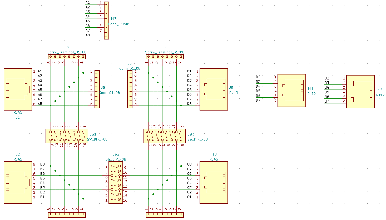
Schematic
It would almost have been possible to design the PCB without a schematic, but having the schematic present was helpful to ensure none of the signal lines got swapped.
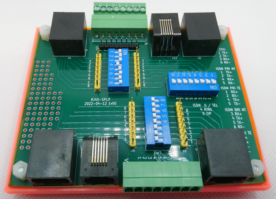
This board has 4x RJ45 connectors and two RJ12 connectors.
There are also pin headers and screw terminals for temporary connections, and DIP switches to allow the connections between the sockets to be isolated.
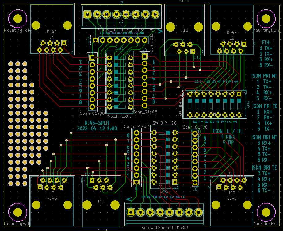
PCB
The PCB was routed very quickly. The main use for this project was intended to be for telecoms projects, so no particular care was taken with trace impedance or differential routing etc.
I added a small prototyping area to some spare space on the board, but this prototyping space was so small I've not found it to be very useful (and I also forgot to remove the soldermask, making it even less useful).
Slightly more careful routing of J1 (to increase the available space), plus removal of the soldermask over the prototyping area would be worth considering if building this project.
Also, note - when constructing, DIP switches usually have numbers printed on them. Ensuring that these numbers line up with the numbers on the silkscreen will make the board much easier to use.
KiCAD project files: rj45_split_pcb.zip
Mechanical
The PCB is designed to a size of 100mm * 80mm.
This means that inexpensive extruded aluminium enclosures can be used as a housing.
One low cost alternative to this is a 3D printed case I designed in OpenSCAD.
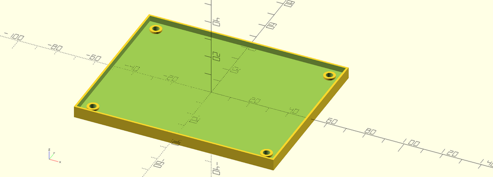
This case also stacks (just about!) - although this may need adjusting, based on the tolerances on your 3D printer.
You may also wish to use the "roundedcube" OpenSCAD script in place of the plain "cube".
OpenSCAD (and STL) files: rj45_split_cad.zip
You'll need to print 4x rj45_split_foot.stl, 1x rj45_split.stl and use M3 nuts and bolts to assemble it.